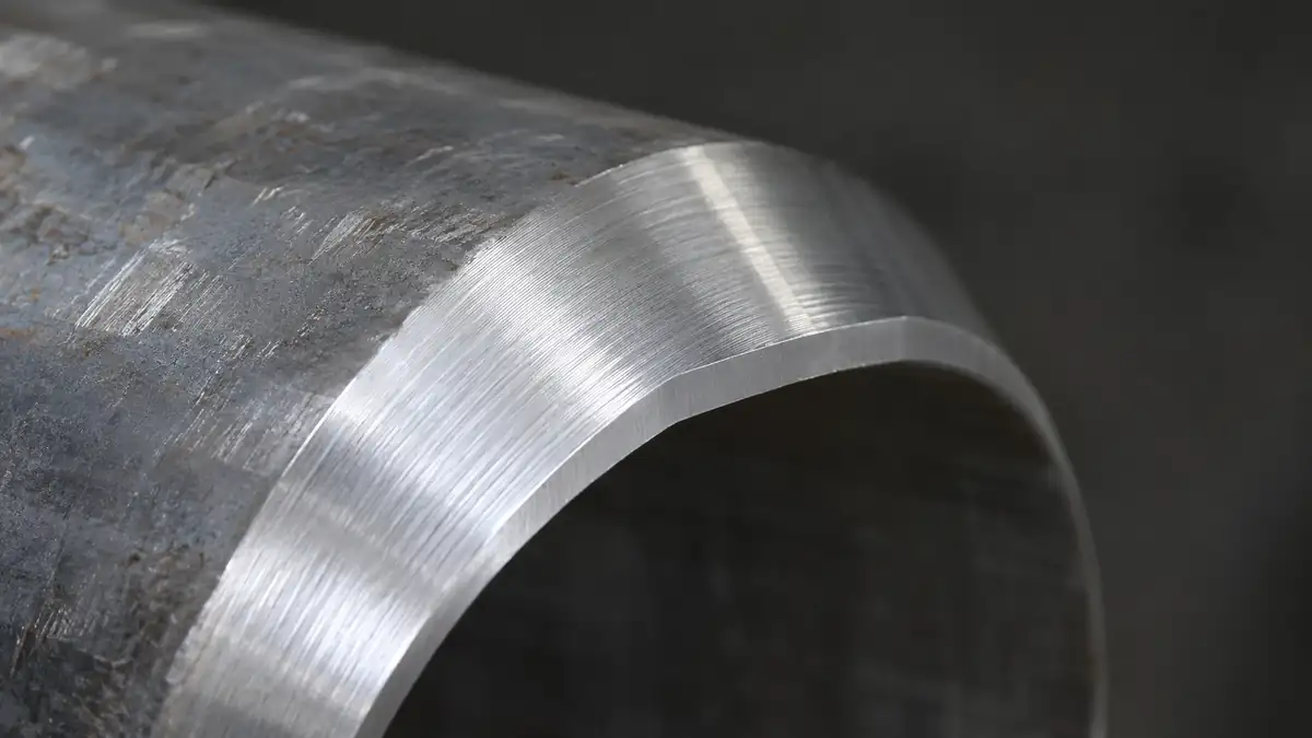
The standard butt-weld end for steel pipe is a 37.5° ± 2.5° bevel with a 1.6 mm ± 0.8 mm root face (land), as given in ASME B16.25 for wall thicknesses up to 22 mm. Above 22 mm, B16.25 uses a compound bevel: 37.5° for the first 19 mm from the outside surface, then 10° ± 1° down to the land. The compound shape keeps the groove from becoming too wide, which saves filler metal and welding time.
Why 37.5° and not 45°?
Two pipes with 37.5° bevels form a 75° included angle. That is wide enough for the welder or the torch to reach the root and fuse the side walls, but narrow enough that the groove does not fill up with unnecessary weld metal. A 45° bevel (90° included) adds roughly a third more cross-sectional area for the same wall, with no gain in access for most processes.
A 30° bevel (60° included) is common in some pipeline and automatic welding procedures, where a narrow groove and a controlled process make access less of an issue. Always follow the welding procedure specification (WPS) for the job; the bevel geometry is part of the qualified procedure.
The land and the root gap
The land is the flat, unbeveled part at the inside of the wall. It supports the root pass and stops burn-through. Too small a land and the root melts through; too large and the root will not fully penetrate. The root gap — the space between the two lands at fit-up — is set by the WPS, typically 1.5–3 mm for manual root passes.
Compound bevels on heavy wall
On a 40 mm wall, a single 37.5° bevel produces a groove more than 60 mm wide at the cap. The compound bevel in B16.25 steps down to 10° after the first 19 mm, so the groove gets deeper without getting much wider. J-bevels achieve the same result with a radius at the root and are common in power-plant piping.
| Wall thickness | Typical bevel (ASME B16.25) | Land |
|---|---|---|
| Up to 22 mm | Single 37.5° ± 2.5° | 1.6 ± 0.8 mm |
| Over 22 mm | 37.5° to 19 mm depth, then 10° ± 1° | 1.6 ± 0.8 mm |
How do you produce a consistent bevel?
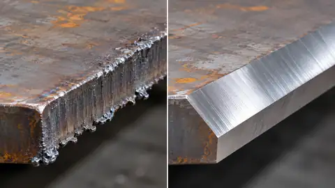
Grinding by hand gives an angle that changes around the circumference. Torch cutting leaves an oxidised surface and a heat-affected zone that usually has to be ground back, especially on stainless and alloy steel. A pipe beveling machine cuts the bevel and land with a fixed tool at a fixed angle, so every point around the pipe end has the same geometry.
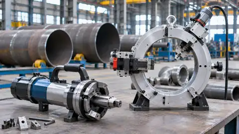
- ID-mounted bevelers lock into the bore and are the quickest choice for open pipe ends in the shop or on site.
- Split-frame OD-mounted machines clamp around installed pipe, cut and bevel at once, and are used for maintenance and tie-ins.
Estimate weld metal for a single-V groove
The groove cross-section for a single-V joint (excluding cap reinforcement) is approximately A = g·t + (t − c)² · tan(α), where t is wall thickness, c the land, g the root gap and α the bevel angle per side. Multiply by 7.85 g/cm³ for steel. Use the calculator below to compare bevel angles for your wall thickness.
Frequently asked questions
What is the standard bevel angle for pipe welding?
37.5° ± 2.5° per side with a 1.6 mm ± 0.8 mm land, giving a 75° included angle, per ASME B16.25 for walls up to 22 mm.
When is a compound bevel used?
ASME B16.25 specifies a compound bevel for walls over 22 mm: 37.5° for the first 19 mm, then 10° to the land, to limit groove width and filler metal.
Can I use a 30° bevel instead?
Yes, if your qualified welding procedure specifies it. 30° bevels are common for some pipeline and automatic welding procedures.